The practical answer.
First measure current in the battery branch and record input, system-load and temperature conditions together. Low battery charge current can be an intended response to the charger state, limited input power, device load or temperature regulation. A charging indicator alone does not identify the cause. Compare the same approved setup on the bench and in the enclosure before altering current-programming components.
- USB input current is not automatically battery charge current.
- Charger die regulation and battery-temperature sensing are different measurements.
- A single-cell charger example does not approve charging a two-, three- or four-series pack.
Define where the reported current was measured
A report saying the battery only charges at a small current is incomplete until the measurement point is identified. An inline USB meter observes input behavior. A battery-branch measurement observes current entering or leaving the battery. A software register may report a filtered estimate. The same device can show different values at these points without any instrument being defective. Draw the power path and label the measured branch before comparing the result with a programmed charger setting.
Repeat the observation with the display, radio and processor states recorded. If the device consumes energy while connected to an adapter, some available input power serves the system. TI's BQ24074 family illustrates a power-path architecture that can adjust battery charging while supplying the load. That is an example of a documented mechanism, not a claim that a Jetray pack contains that IC or that it is appropriate for every pack configuration.
Separate the regulation mechanisms
The question is not simply whether a charger is hot. A charger may regulate its internal die temperature, while a separate thermistor interface monitors battery temperature. TI documents these as different functions in the BQ2407x family. An acceptable enclosure-air reading does not establish either measured quantity. Read the exact charging IC's status behavior, circuit implementation and current documentation rather than assuming an indicator LED proves uninterrupted constant-current charging.
Collect battery voltage and current, adapter voltage at the board, system demand and relevant temperatures on the same time axis. Use the approved product limits as the test boundary. A larger nominal adapter rating does not guarantee adequate voltage at a connector after cable loss, nor does a larger programmed charge current guarantee a shorter charge under thermal constraint. Avoid defeating temperature sensing or protection to obtain a more attractive current trace.
| Observation | Question to resolve | Useful evidence |
|---|---|---|
| Input current rises but battery current falls | Did system demand change? | Aligned load and battery traces |
| Current changes after housing closure | Did thermal or electrical conditions change? | Matched open/closed device runs |
| Status says charging but no useful charge flows | What does that IC's status actually mean? | Datasheet state and measured battery branch |
| Behavior follows cable substitution | Is input voltage reaching the intended circuit? | Voltage at board connector under load |
Use a conditional power estimate to prioritize measurement
For a deliberately simplified linear-charger example, a 5.0 V input, 3.6 V battery and 0.5 A battery current imply about 0.7 W from the voltage difference times current. This omits system-path losses, control consumption and other circuit details. It is not a thermal prediction, and these inputs are not Jetray product ratings. The estimate explains why changing enclosure heat flow can matter even when battery current appears modest.
Do not convert that estimate directly into a cell temperature. Board copper, placement, neighboring components and the actual charger topology matter. Use the calculation to choose measurement points and prioritize a controlled comparison. If a switching charger is fitted, use its appropriate efficiency and dissipation model rather than applying the linear example. The electrical design owner should confirm the model before a purchasing team concludes that the battery is responsible for the charging delay.
Run a comparison that can explain the difference
A useful result identifies both what changed and what did not. If a later run used a different charge state, a quieter firmware build and a new adapter, it cannot isolate the enclosure effect. Preserve the starting conditions and timestamps. When practical, instrument a representative production assembly rather than a sample with exposed boards, temporary wires and a missing cover that substantially change the electrical and thermal environment.
- Freeze the approved charger circuit, firmware, battery identity and starting condition.
- Record instruments, measurement points and any burden introduced in the battery path.
- Capture an approved charging run with a defined system workload and input supply.
- Repeat in the finished housing with the same workload and comparable starting condition.
- Change one suspected cause at a time and preserve the original trace.
- Review the result against the correct cell, pack and charger documentation before revising settings.
Give the supplier a diagnostic packet rather than a faster-charge request
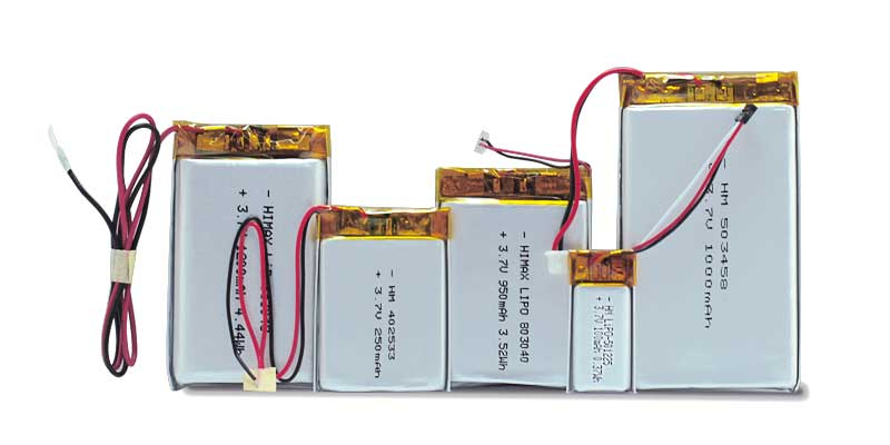
Send a concise description of the observed symptom, pack identity, charger architecture, test conditions and traces. State the business target separately: for example, a required recharge window under a defined use pattern. Ask which supplied battery limits and sensing configuration apply. Jetray's polymer catalogue includes two-series and three-series references; the single-cell TI example in this article must not be applied directly to those series packs. Their charger and monitoring arrangements require their own review.
Keep a system-level issue from becoming an undocumented pack substitution. A change to capacity, temperature sensor, connector or protection design can affect more than charge time. The decision should explain whether the fault was reproduced, the mechanism confirmed and the proposed change validated. If evidence is missing, keep the finding open instead of presenting a speculative cause as a completed root-cause analysis.
Frequently asked questions
Can a charging LED remain on while charge is limited?
Yes, depending on the IC and circuit. Consult its documented status behavior and measure battery current. The indicator alone does not establish the charge phase or explain a limit.
Should we disable the thermistor for a quick comparison?
Do not bypass a safety-related sensing function as a routine diagnostic shortcut. Use an approved validation procedure and resolve sensor placement, wiring and supported thresholds with the design owner.
Does this article specify an approved Jetray charging current?
No. Obtain the exact finished-pack specification. The product references provide an inquiry starting point, and every numerical example here is conditional arithmetic.
Sources & further reading
- TI BQ2407x charger datasheet: power path, thermal and battery-temperature functions ↗
- VARTA CellPac LITE handbook: use individual battery charging specifications ↗
AI-assisted educational diagnosis framework, not an approved charging procedure. No personal engineering credential, Jetray charger implementation or measured performance is asserted.
Prepared for the lithium polymer batteries collection. General engineering guidance does not replace a model-specific datasheet or application validation. Source review: 5 November 2026.