The practical answer.
A protection circuit monitors specified fault conditions; it does not define the equipment's normal shutdown, data preservation or user recovery sequence. Approve those behaviors separately, using the exact pack and circuit configuration. A device should not rely on a protective trip as its everyday low-battery control strategy, nor assume that connecting any charger will always restore operation in the same way.
- Normal application shutdown and protective interruption need separate requirements.
- Recovery conditions depend on the actual protection, charger and load implementation.
- Do not create fault tests by abusing real cells; use qualified facilities and approved simulation methods.
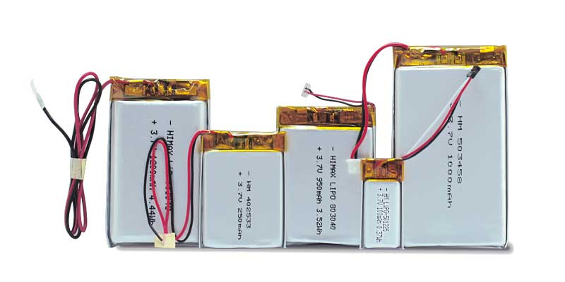
Assign ownership of each behavior
A product may have an application-level low-battery warning, a regulator undervoltage function, a charger and a pack protection circuit. These functions can respond at different times and observe different nodes. Write down which function requests orderly shutdown, which preserves data and which limits an abnormal electrical condition. A single requirement saying protected battery fitted leaves these interfaces undefined and can produce a device that repeatedly restarts after apparently shutting down.
TI's BQ297xx documentation provides an example of a single-cell protector with voltage and current fault detection and programmed delays. It is not a general-purpose charge controller or a finished-device specification. Different variants and external components matter. Mentioning that family does not mean it is fitted to Jetray products; the example helps buyers ask for a functional description of the actual supplied assembly.
Describe a normal shutdown sequence before a protective event
Define which user functions must end gracefully, what state is saved and what remains connected after the screen or processor appears off. A radio, regulator divider or always-on sensor can continue drawing current. The requirement should identify the measurement node and load condition used to detect low battery. Otherwise, software and hardware teams may use different voltage assumptions while believing they have agreed on one shutdown threshold.
Consider a conditional example: if a load draws 50 microamps after software shutdown for thirty days, the charge drawn is 36 mAh, calculated as 0.05 mA times 720 hours. This is only a leakage-budget example. It is not an approved storage drain, a prediction of cell voltage, or a safe-discharge limit for a Jetray pack. The calculation shows why off-state consumption belongs in the device requirement rather than being left to the protector.
| Function | Evidence to request | Common unresolved question |
|---|---|---|
| Normal low-battery shutdown | Firmware event and current trace | What remains powered? |
| Protection interruption | Actual pack functional specification | Which fault and delay caused it? |
| Charge restart | Charger and protection recovery description | What conditions permit recovery? |
| Temperature sensing | Sensor identity, wiring and placement | Is the cell or only the board represented? |
| User indication | UI requirements with observed state | Does the message distinguish waiting from failure? |
Test recovery as a state transition
A recovery requirement should identify the initial state, the action taken and the expected stable state. Examples include reconnecting an approved charger after normal shutdown, removing an external supply during active operation, or powering up after an allowed storage interval. These are different cases. Do not describe all of them as waking the battery, because that phrase conceals whether the charger, protector, regulator or firmware is controlling the result.
Use qualified engineering methods to simulate relevant conditions without deliberately overcharging, shorting or deeply discharging real cells on an ordinary bench. A controlled emulator or approved circuit-level test may answer some interface questions; it does not automatically validate the physical battery. Any cell-level abnormal-condition testing requires an appropriate facility, procedure and limits. Record which evidence is a simulation and which uses a real approved pack.

Check for repeated restart rather than one successful reboot
A product that starts once after charger insertion may still have an unstable recovery sequence. Capture supply voltage, battery-path current, regulator state and application events together. Watch for a repeated sequence of startup demand, rail collapse and restart. A recovered no-load voltage can differ from the voltage available during the next startup event. The test should include the permitted peripheral configuration and firmware behavior, not only a minimal bootloader.
Agree what the user sees while the system waits for a valid power state. An ambiguous indicator can encourage repeated unplugging, button presses or unnecessary battery replacement. Engineering acceptance should therefore include a functional record of the UI and event sequence. This is different from a generic prototype-to-production checklist: it concentrates on one specific interface, the transition between off, charging and usable operation.
Approve the actual pack configuration
Request the pack model, series arrangement, relevant protection functional description, temperature-sensor details and connector pinout. Do not infer a single-cell architecture from the word LiPo. Jetray's catalogue includes both 7.4 V 2000 mAh and 14.8 V 3500 mAh references, which require their own approved charging and monitoring arrangements. Neither public voltage class establishes a fault threshold or recovery process.
The release record should connect the pack and firmware revisions to the observed behavior, unresolved conditions and acceptance owner. Ask for change notification when a protection variant, sensor, connector or charger interface changes. A supplier statement that the new board is also protected is not enough to establish unchanged device behavior. Revisit the affected transition tests whenever the interface can change, while keeping untouched evidence clearly identified.
- Name normal shutdown, protection interruption and charging recovery as distinct states.
- Record the exact hardware, pack and firmware configuration.
- Choose safe, approved methods for each transition test.
- Capture electrical traces and user-visible behavior on a shared timeline.
- Check repeated operation and off-state consumption, not only one successful start.
- Release the configuration with explicit remaining conditions and change triggers.
Frequently asked questions
Does the protection circuit replace low-battery firmware?
No. Equipment behavior such as data saving, orderly shutdown and warnings needs its own requirements. Protection functions address the conditions documented for the actual battery assembly.
Can we specify a universal recovery voltage?
No. Recovery depends on the actual protector variant, charger, load and wiring. Request the relevant controlled documents and verify the complete device instead of importing an example threshold.
What should purchasing include in a repeat order?
Identify the approved pack and interface revisions and require notification of relevant changes. Ask whether the quoted configuration matches the samples used for shutdown and recovery verification.
Sources & further reading
AI-assisted interface-validation education. IC examples do not identify components fitted to Jetray packs. No engineer review, fault-test result, certified implementation or product-specific threshold is claimed.
Prepared for the lithium polymer batteries collection. General engineering guidance does not replace a model-specific datasheet or application validation. Source review: 5 November 2026.