The practical answer.
Set a maximum installed battery current from the required storage interval and the charge your wearable must still have at first use. Measure at the battery boundary after the production shutdown sequence, include any pack electronics outside that measurement and verify each approved wake path at the lowest specified starting condition.
- Distinguish software sleep from a verified factory-off state.
- Measure average charge drain with all fitted accessories present.
- Run the first-start sequence using the final hardware and firmware.
Define the boxed state with the production line
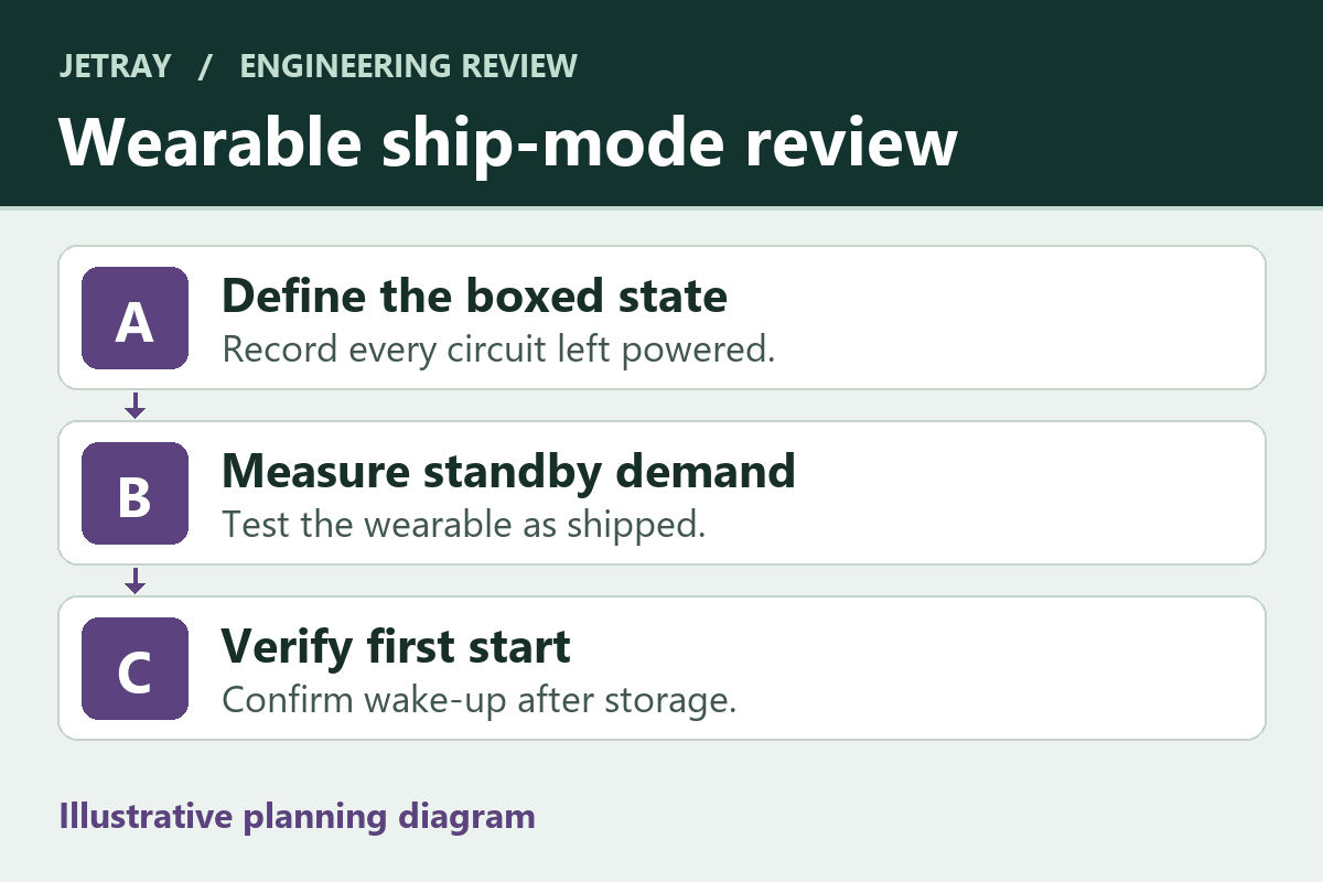
A compact wearable can leave assembly with a fully functional battery and still reach the buyer unable to start. The factory test may leave a radio scanning, a charger in a different mode or a status circuit powered after the display goes dark. Describe the state of the actual boxed unit as a set of observable conditions. List whether the charge dock is connected, which switches are accessible through the enclosure, what the firmware records and which supplies should be off.
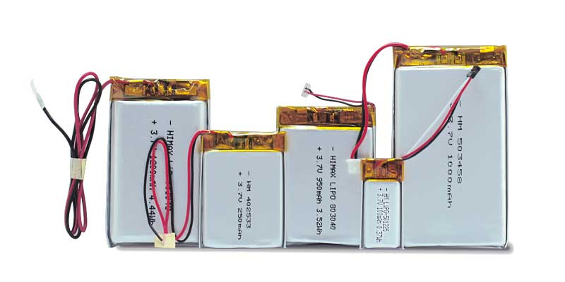
Jetray’s polymer materials describe thin and shaped packs for device development. When the enclosure drives a custom shape, discuss mechanical fit and the electrical off state together. A connector that can only be reached before final assembly affects how the line confirms ship mode. A sealed enclosure also influences whether first start is by a button, the approved charger or another documented input.
Turn a storage interval into a current limit
Keep the accounting in milliamp-hours. A constant 12 µA at the battery connector over 90 days consumes about 25.9 mAh: 0.012 mA multiplied by 2,160 hours. If an illustrative electronics allowance is 18 mAh for that interval, the budget is about 8.3 µA average. That is a host-side design example. The actual project must assign separate margins for starting charge tolerance, pack-side circuitry outside the measurement, storage conditions and cell self-discharge.
Average current must include periodic activity. A test that measures only the quiet portion between pulses can understate consumption. If firmware wakes on a timer, measure over enough complete periods to account for both the brief active state and the long quiet state. Keep the duration and capture settings with the measurement so the next board revision can be compared on the same basis.
Measure at a boundary that captures the fitted device
Select a measurement setup whose burden voltage and current range are appropriate for the circuit. Capture battery connector voltage along with current if the instrument can affect the state. Look at the trace from the shutdown action through settling and at the end of the chosen observation window. A changing current range or a supply interruption can reset the device, so include those conditions in the test record.
Texas Instruments documents a distinct ship mode for the BQ2512x family and shows how its wake conditions depend on input and battery state. Treat that as an example of why an IC figure cannot serve as the assembled wearable’s budget. A board can have leakage paths, protection and optional subassemblies beyond the chip’s measurement conditions.
| State | Observe | Record |
|---|---|---|
| End of factory test | External supply removed in the intended sequence | Hardware and firmware revision, exact command and fixture state |
| Boxed device | Settled current plus any periodic events | Battery voltage, observation interval, instrument range and computed average |
| First user start | Approved wake input restores the intended behavior | Starting battery condition, initial response, time to normal operation |
| Interrupted start | Weak adapter or incomplete wake attempt | Recovery path, repeatability and instructions for the user |
Close the gap between low drain and a usable first wake
Verify first start at the lower expected stored charge and after a representative delay. Test each supported user action with the enclosure closed. If wake depends on an adapter, include the approved cable and supply in the matrix. If a switch can wake the device accidentally during packing, define how the line will detect an unintended wake and restore the intended state.
Give a pack supplier the enclosure drawing, charger requirements, acceptable starting voltage conditions and the intended factory-off sequence. Compare the polymer references below as examples of different pack envelopes and voltage classes. The project still needs the proposed sample’s own specification and a measurement in the finished device.
Catch an incomplete shutdown before the packaging step
Choose what the production line can check on every unit and what belongs in an engineering audit. For example, a fixture may confirm that the device accepted the shutdown command and that current drops into the expected range after the cable is removed. Engineering can then verify the longer observation window that detects infrequent wake events. Correlate the short check with the long test before treating it as a release criterion. Retain the fixture script revision so a future cable or firmware change can be traced back to the last validated sequence.
Questions that belong in the wearable release review
Does a dark screen prove the unit entered ship mode?
Confirm with the agreed electrical measurement and state record. Some designs retain active circuits while the display and application firmware appear inactive.
Should the fixture use a bench supply for every check?
Use a supply or simulator for defined boundary conditions as agreed by the engineers. Include checks with the approved battery assembly to capture the actual protection, connections and wake behavior.
What changes should trigger another first-start check?
Review changes to the charger IC or firmware, pack protection, battery connector, board leakage paths, optional modules and the packing sequence. Record which change was checked and which revision passed.
Sources & further reading
- Texas Instruments BQ2512x data sheet, ship mode and electrical characteristics ↗
- Texas Instruments technical article on putting portable products in ship mode ↗
- Jetray lithium polymer product family ↗
Source review 5 November 2026. The charge calculation is an original planning example. It does not describe a Jetray test, battery or specified storage limit.
Prepared for the lithium polymer batteries collection. General engineering guidance does not replace a model-specific datasheet or application validation. Source review: 5 November 2026.