The practical answer.
A charger IC can reduce current when its own die gets hot. Battery temperature qualification uses a separate measurement path, such as a pouch sensor feeding the charger’s temperature input or a pack control. Verify both paths because a cool charger board does not show that a pouch is within its permitted charge range.
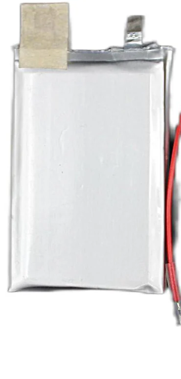
Which temperature does the charger regulate?
A linear charger dissipates power as it drops input voltage to the battery voltage. As a first approximation, charger dissipation rises with charge current and that voltage difference. The package, PCB copper and enclosure determine how much the die warms. Some ICs reduce current as junction temperature approaches an internal threshold. Others expose different controls or status indications. Read the exact part and revision before assigning a response.
The Texas Instruments BQ24064 is a single-cell charger example. TI lists IC thermal regulation and a separate battery temperature thermistor function. Its junction loop reduces current under high die temperature, while its battery temperature input separately qualifies whether charging is permitted. The Analog Devices LTC4054 datasheet is another example of junction-temperature feedback. Neither source specifies the charger inside a Jetray product or qualifies a multi-cell pack.
Test matrix for separating charge IC and battery temperature responses
| State to reproduce | Trace to retain | Decision to document |
|---|---|---|
| Board warms while pouch sensor stays in range | Input voltage, current, package or PCB temperature and battery sensor reading | Confirm the current reduction tracks IC regulation or the actual charger limit. |
| Battery sensor crosses the configured boundary | Pack surface reading, temperature input, charge status and current | Record whether this design reduces current, suspends charging, or sends a control command. |
| Temperature-sensor open or short | Injected condition via a rated test fixture, fault state and charge current | Confirm the selected circuit enters its specified fault state. |
| Temperature returns to the permitted window | Threshold crossings, delay, current and host status | Record hysteresis, restart conditions and whether a reset is needed. |

What should the pouch temperature sensor measure?
Choose a repeatable sensor position with the cell or pack supplier and document the contact material, attachment method, cable routing and measurement uncertainty. Nearby displays or power electronics may make the board and pouch follow different temperature curves. Validate the sensor’s response and lag in the assembled product at the declared charge rate and worst credible thermal conditions. Distinguish a board temperature used for system control from the battery temperature measurement used to qualify charging.
Specify the permitted charge window, who enforces it, the action at each boundary and the recovery rule. If the design uses a thermistor divider, verify the actual sensor curve and tolerances together with the charger input thresholds. If the pack or host sends a charge-inhibit signal, record which device controls the charger and what happens when the signal is missing. Limits and fault behavior must come from the selected cell, pack and charger documentation.
How should the lab diagnose reduced current?
Capture input voltage, battery voltage, current, charger state and independent board and pack temperature traces on one time base. A lower current alone cannot identify junction regulation, a hot battery, source-current limiting or the normal constant-voltage tail. Reproduce one condition at a time within the approved test plan. Use a suitable electrical fixture for fault simulation and avoid inducing battery faults by heating or modifying a live pouch.
Record the enclosure revision, firmware, sensor position, input source, initial state of charge and ambient temperature so another reviewer can repeat the run. Reopen verification after moving the sensor or changing the charger, PCB, enclosure, battery configuration or nearby heat source.
What belongs in the engineering handoff?
Send the selected charger and pack references, a marked sensor drawing, charge current and voltage conditions, temperature-source definitions, and representative logs showing both thermal paths. Use Jetray catalogue entries as starting points for dimensions and configuration. Request controlled specifications and verify fit for the exact product before release.
Sources & further reading
- Texas Instruments BQ24064 product and datasheet, IC regulation and battery thermistor input ↗
- Analog Devices LTC4054 datasheet, junction-temperature feedback ↗
- Jetray LiPo battery product family ↗
- Jetray 11.1 V 2300 mAh product reference ↗
Prepared for the lithium polymer batteries collection. General engineering guidance does not replace a model-specific datasheet or application validation. Source review: 9 November 2026.